Engineering relief map for 6 zones
The working geometry of the microrelief is to control two forces: wind, which must be slowed down, and water, which must be caught and absorbed.
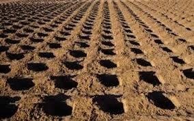
Microrelief
Every meter must catch water or break the wind
All lines are placed across the prevailing wind, and the trenches follow the contour without downward drainage. A uniform topography throughout the entire site is a mistake: each zone requires its own geometry.
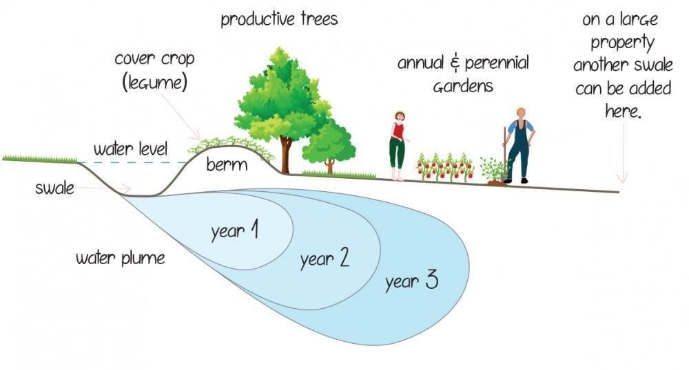
Water distribution zone: contour trenches and planting basins.
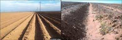
Anti-dune zone: net, barriers and lines strictly across the wind.
Parameters by zones
| Zone | Target | Form | Working dimensions |
|---|---|---|---|
| 1: 0-30 m | salt, aerosol, maintaining infiltration | micro-holes, stone half-rings, low berms | holes 10-20 cm deep, 40-80 cm in diameter; step 1-2 m |
| 2: 30-100 m | salt barrier and sand stabilization | half-wells + cells | radius 1-2 m, side 20-40 cm, step 2-4 m |
| 3: 100-300 m | soil activation and water retention | half-moons + zai-pits + short trenches | pits 30-60 cm in diameter, trenches 30-50 cm |
| 4: 300-800 m | accumulation and distribution of water | swales + landing pools | trenches 50-80 cm deep, 50-100 cm wide |
| 5: 0.8-2 km | productive zone | wide swales, terracing, deep pits | swales 1-2 m wide, pits 80-120 cm |
| 6: 2-5 km | stop sand before the system | mesh, wave crests, long barriers | cells 1 x 1 or 2 x 2 m, barriers 30-60 cm |
How to take wind and water into account
wind: lines across the flow, gradual reduction in speed, no long open corridors
water: collection, slowing, absorption, retention
Zone 6: Mesh and barriers to the main system
zones 3-4: half-moons, zai-pits and trenches
Zone 5: Swales and landing pools
Final formula
The relief is the project's skeleton, the plants its skin. Without the right geometry, even good views will be weakened by the water receding and the wind returning the sand.